


The 100DSV DRAG® Spray Water Control Valve gives thermal power plant operators exceptional control over steam temperatures, allowing them to operate their plant safely, reliably and efficiently.
Benefits of 100DSV
Product Specifications
Pressure rating
Body configuration
Maximum design temperature
Rangeability
Shutoff
Steam temperature control
The control of steam temperatures is of vital importance for safe, reliable, and efficient operation of a thermal power plant. Attemperator spray control valves are the final control elements for the superheat & reheat temperatures. They are critical components responsible for fine tuning steam temperature control. A well-tuned steam temperature control maintains the throttle temperature at the set point resulting in an efficient turbine operation.
Materials
| Components | Materials of Construction |
| Body | A216 WCB/WCC |
| Bonnet | A105 |
| Seat Ring | 316 SS |
| Spindle | 17-4PH, Heat Treat |
| Disk Stack | 410 SS, Heat Treat (Standard) / Inconel 718, Heat Treat (HTR) |
| Balance Seal Only 1” & 1.5” trim sizes | Glass Filled Teflon |
| Stem Packing | Glass Filled Teflon OR graphite |
| Gasket | Graphite / Stainless Steel |
Technical details
| Pressure Rating / ASME B16 | 2500 |
| Body Configuration | Angle or Globe (through) |
| Maximum Design Temperature | 500°F (260°C) 4 |
| Flow Direction | Over-the-plug (Flow-to-close) |
| Rangeability | 30:1 (Standard) / 50:1 (HTR) 4 |
| Actuator | Spring Diaphragm with Positioner & Filter Regulator |
| Failure Mode | Fail Close or Fail Open (Standard) / Fail-in-Place (Optional) |
| Manual Override (Optional) | As shown |
| Position Feedback Transmitter (Optional) | Output signal = 4-20 mA (Integral) |
| Positioner Demand | Input signal = 4-20 mA |
| Limit Switches (Optional) | Double pole/Double throw |
| Shutoff | ANSI/FCI 70.2 Class V |
Notes:
1. All buttweld end connections in accordance with ASME B16.25.
2. All socket weld end connections in accordance with ASME B16.11.
3. Use IMI Critical Engineering’s program for sizing and selection.
4. Custom designs available to meet any special requirements related to sizing, performance, piping configuration, etc. Please contact us for details.
Dimensions
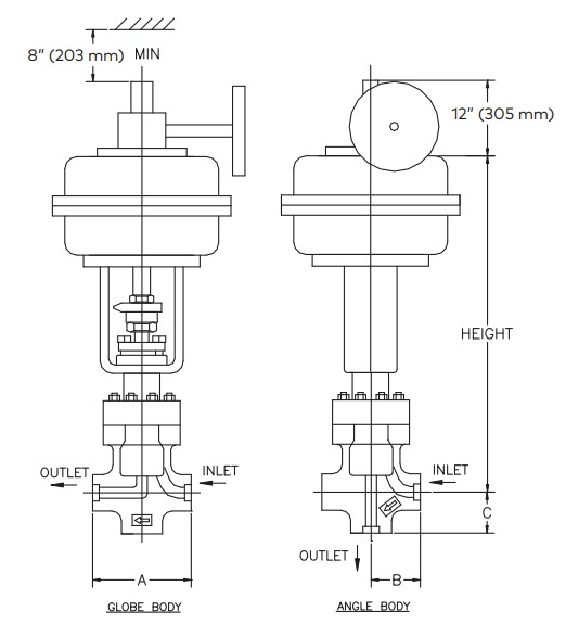
Standard
| Dimension in (mm) | Nominal Size: 1“ | Nominal Size: 2“ | ||
| Trim: 3/8“, 5/8“, 1“ | Trim: 1.5“ | |||
| Angle | Globe | Angle | Globe | |
| A | - | 8.50” (216 mm) | - | 11.50” (292 mm) |
| B | 4.25” (108 mm) | - | 5.75” (146 mm) | - |
| C | - | 3.50” (89 mm) | - | 4.50” (114 mm) |
| Weight | 500 lbs (230 kg) | 750 lbs (340 kg) | ||
| Height | 34” (864 mm) | 37” (940 mm) | ||
| Max Rated Cv 4 | 1.1 | 4.1 | 11.5 | 27 |
| Valve Stroke | 1.5” (38 mm) | 2.5“ (64 mm) | ||
| BW Connection Per ASME B16.25 | 1“, 1.5“, 2“, 2.5“, 3“ SCH 40, 80, 160 & XXS | 2“, 2.5“, 3“, 3.5“, 4“ SCH 40, 80, 160 & XXS | ||
| SW Connection Per ASME B16.10 | 1“, 1.5“, 2“ SCH 40, 80, 160 & XXS | 2“, 2.5“ SCH 40, 80, 160 & XXS | ||

Figure 1: An example of a typical spraywater system schematic. The IMI CCI 100DSV DRAG® valve is engineered to exceed the demands of these severe service applications.
 ERP
ERP